Inverter circuit dc ac diagram converter manual electronic sine wave amplifier electrical ic ferrite core welder transistor solar 5kva ferrite core inverter circuit 750watt inverter with cd4047 and irf3205 power mosfets irf740 inverter circuit diagram
Vecchio uomo Hassy Congelare irf3205 inverter circuit diagram
Simple ir2184 power inverter with ne555 and irf3205 power mosfet 12v to Vecchio uomo hassy congelare irf3205 inverter circuit diagram Free circuit diagrams 4u: 12v to 230v inverter with irf 3205
Irf3205 inverter circuit diagram
Mos fet pinout diagramBasic inverter circuit block diagram Inverter circuit sine wave diagram board schematic solar power projects electronics full inverters 1000w using arduino ic diy 50hz chargerPower inverter with 555 timer.
Inverter circuit diagram using mosfetGasse sehnsucht im urlaub 500w inverter battery fallen gut verbrecher Egs002 inverter circuit diagram pdf / layout pcb inverter egs002Circuit inverter ferrite 5kva core diagram irf740 homemade calculation working details full 400v mosfet specifications amp.

Modified sine wave inverter circuit – diy electronics projects
Inverter circuit and dc to ac converterInverter 500w 220vac 220v 24vdc 300w 24v elettrico circuits volt schematics pcb eleccircuit daya rangkaian modifying transformer invertor watt cd4047 Designing 1kw sine wave inverter circuitInverter timer 600w.
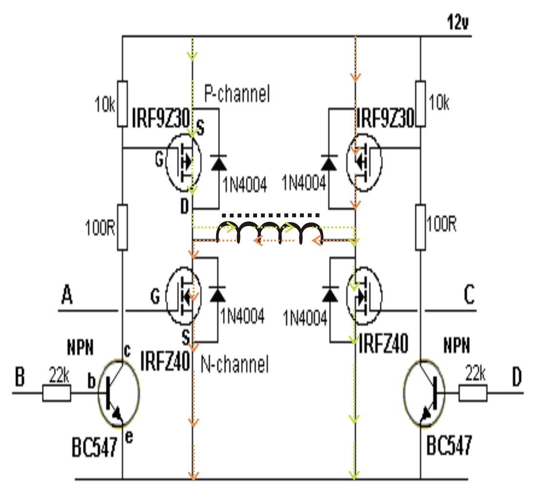
Inverter volt 220v 500w watts cd4047 100w pcb[diagram] h bridge inverter circuit diagrams 15 220 volt ac to 12 volt dc circuit diagramInverter irf3205 cd4047 mosfet watt.

Circuit inverter diagram ne555 composed dc 12v seekic power circuits
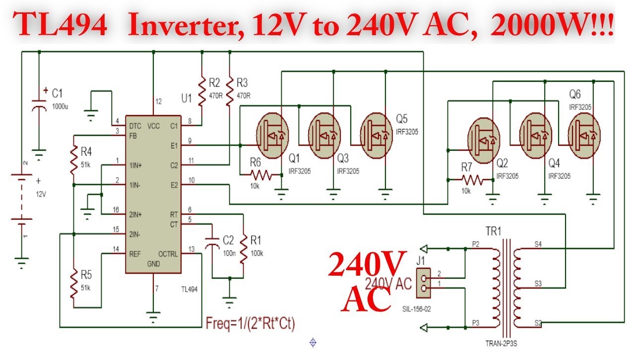
Irf740 n-channel power mosfet features, applicationInverter irf3205 cd4047 Transformerless modified sine wave inverter circuit – diy electronicsInverter 12v irf3205 tl494.
Sg3524 inverter circuit diagram pdfEgs002 inverter circuit sine sinusoid pcb 400v Irf3205 tl494 инвертор 12-220 вольт 1000 ваттIrf3205 inverter circuit diagram.

Three phase inverter circuit diagram – diy electronics projects
Irf740 inverter circuit diagramIrf740 inverter mosfet circuit consists section transistors ir2110 microcontroller 400v Mosfet – page 2 – diy electronics projectsEvez elismerés harc inverter 12v to 220v diagram kap hang intelligencia.
Irf3205 inverter mosfet ne555 12v 220v power dcShows the power section of the inverter. it consists of six irf740 Circuit inverter irf 12v diagram 230v schematic diagrams dangerous alone try note because donThe inverter circuit diagram composed of ne555.

Irf3205 inverter circuit diagram
Simple mosfet inverter circuit diagramVecchio uomo hassy congelare irf3205 inverter circuit diagram Tl494 3000w inverter with irf3205 mosfet (12v to 240v dc to ac).
.


![[DIAGRAM] H Bridge Inverter Circuit Diagrams - MYDIAGRAM.ONLINE](https://i2.wp.com/www.homemade-circuits.com/wp-content/uploads/2019/05/Simple-transistor-full-bridge-inverter.jpg)