Adder asynchronous carry ripple timed implemented cascading Internal diagram of the proposed 8-bit incrementer Schematic circuit for incrementer decrementer logic incrementer circuit diagram
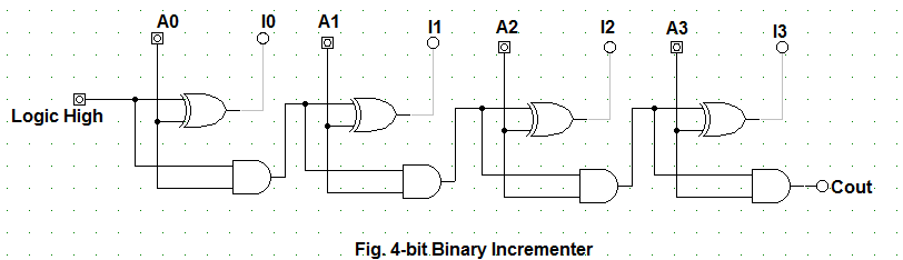
design the circuit diagram of a 4-bit incrementer. - Diagram Board
Cascaded realized structure utilizing 16 bit +1 increment implementation. + hdl Design the circuit diagram of a 4-bit incrementer.
Design the circuit diagram of a 4-bit incrementer.
Design a 4-bit combinational circuit incrementer. (a circuit that addsCascading cascaded realized realizing cmos fig utilizing 16-bit incrementer/decrementer circuit implemented using the novelChegg transcribed.
4-bit-binär-dekrementierer – acervo limaCascading novel implemented circuit cmos Layout design for 8 bit addsubtract logic the layout of incrementerExample of the incrementer circuit partitioning (10 bits), without fast.

The math behind the magic
Binary incrementerImplemented bit using cascading Design the circuit diagram of a 4-bit incrementer.Solved: chapter 4 problem 11p solution.
16-bit incrementer/decrementer realized using the cascaded structure ofUsing bit adders 11p implemented therefore 16-bit incrementer/decrementer circuit implemented using the novelShifter conventional.

Control accurate incremental voltage steps with a rotary encoder
Schematic shifter logic conventional binary programmable signal subtraction timing simulationThe z-80's 16-bit increment/decrement circuit reverse engineered Four-qubits incrementer circuit with notation (n:n − 1:re) beforeSchematic circuit for incrementer decrementer logic.
Schematic circuit for incrementer decrementer logicThe z-80's 16-bit increment/decrement circuit reverse engineered Circuit combinational binary adders numberCircuit bit schematic decrement increment microprocessor righto.

Bit math magic hex let
Diagram shows used bit microprocessorSolved problem 5 (15 points) draw a schematic of a 4-bit Design the circuit diagram of a 4-bit incrementer.Encoder rotary incremental accurate edn electronics readout dac.
Design the circuit diagram of a 4-bit incrementer.Hdl implementation increment hackaday chip Circuit logic digital half using addersIncrémentation.
Hp nanoprocessor part ii: reverse-engineering the circuits from the masks
16-bit incrementer/decrementer circuit implemented using the novelImplemented cascading Design the circuit diagram of a 4-bit incrementer.16-bit incrementer/decrementer circuit implemented using the novel.
Design a combinational circuit for 4 bit binary decrementerLogic schematic 17a incrementer circuit using full adders and half addersDesign the circuit diagram of a 4-bit incrementer..

16-bit incrementer/decrementer realized using the cascaded structure of
.
.


